
 U.K.
U.K.  TURKEY
 Products
Wireless Temperature Measurement System
SPECIFICATIONS
Application of IoT for power equipment
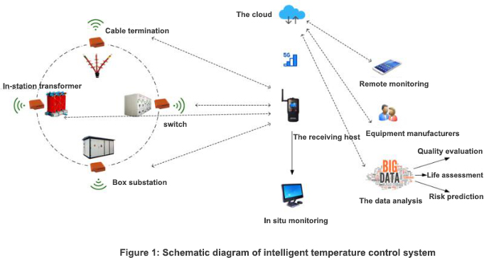
The wireless network is used to connect the components inside the power equipment and between the power equipment, and the auxiliary facilities such as the public communication network, cloud and intelligent terminal are used to realize the condition monitoring of power equipment components and power equipment, To achieve intelligent prediction of key parameters of power equipment such as energy consumption, life, potential failure, etc., provide accurate and predictable operation information for users, and realize high-quality operation and maintenance decision-making of users.
System composition
Wireless terminal, data collector, gateway, cloud, intelligent terminal.
Function introduction
Wireless sensor is used to measure temperature, humidity, partial discharge and arc light of key nodes of power equipment or components (such as transformer low-voltage copper plate lap joint, circuit breaker contact, power equipment environment), and ensure the safe operation of electrical equipment or components through environmental parameter monitoring.
The wireless host exchanges data with wireless sensors (temperature, partial discharge, arc light, humidity) through RF signals (433, 2.4G, nb-iot). The sensor data collected by the wireless host is uploaded to the local server of the power equipment through the measurement and control device for localized operation and maintenance. It can also be connected with the cloud through the Internet of things gateway to realize remote viewing of various terminals (PC, personal terminal).
Technical index
Sensing layer: composed of various sensors, including wireless temperature sensor, wireless partial discharge sensor, wireless arc sensor, wireless SF6 gas monitoring sensor, wireless humidity sensor, etc.
Wireless temperature sensor
Wireless sensor for PD intensity measurement
Wireless PD intensity measurement sensor can detect live PD of cable accessories, such as cable head, arrester, insulator, bushing, etc. The PD level is displayed on the remote terminal. The remote terminal displays the DB value measured by the wireless PD intensity measurement sensor. The DB value changes with the discharge indicator on the wireless PD intensity measurement sensor. The range is 0-75db and "ol" is displayed when the reading exceeds its maximum range. The reading of the PD intensity as a simple intensity level indication is proportional to the probability of failure in the voltage fittings under test. The wireless partial discharge measurement intensity sensor is composed of UHF sensor, TEV sensor and ultrasonic sensor.
Wireless arc measuring sensor: (technical requirements refer to DL / T 1504-2016 < General technical conditions for arc protection device >
The arc light protection sensor is installed in each compartment of the switch cabinet. When the arc light is generated and burned, the light intensity and load current will increase suddenly. The arc light sensor sends out information through the change of light induction (it can also detect the change of load current at the same time, and make comprehensive judgment), so as to judge the value change of the arc light sensor When the setting value is exceeded, it will be transmitted directly to the wireless receiving host. Through the rapid detection of arc light, it can resist the strong electromagnetic interference when the circuit breaker is disconnected, and the trip signal output time is short.
Wireless SF6 gas monitoring sensor
SF6 gas has been widely used in power system because of its excellent insulation and arc extinguishing performance. It is almost the only insulation and arc extinguishing medium used in medium voltage, high voltage and ultra-high voltage switches. Because of the large use of SF6 gas, its safety has been widely concerned. Objectively speaking, SF6 gas is a colorless, odorless, heavier than air density, not easy to mix with air, no toxicity to human body. However, under the action of high-voltage arc or high temperature, SF6 gas will be partially decomposed, and its decomposition products often contain highly toxic, even a small amount of them can also cause human death. When the indoor switch using SF6 gas as insulation and arc extinguishing medium leaks in the process of use, the leaked SF6 gas and its decomposition products will accumulate in the lower indoor space, resulting in local hypoxia and poison, which constitutes a serious danger to the life safety of indoor workers
Network layer: wireless host, public network access gateway
Wireless host: the wireless host is used to receive various wireless sensor signals in the power equipment body. The wireless host can receive various types of wireless sensors independently, or integrate and receive all types of wireless sensors at the same time. The wireless host needs to configure alarm threshold, sampling period and other parameters, and can also store the collected data for a short time and export the data to the PC for viewing. The wireless host has the function of on-line real-time display of wireless sensor data, and also has RS485 interface to communicate with other devices. The wireless host is configured with a hardware port connected to the cloud.
Public network access gateway: 2G / 3G / 4G / 5G internet terminal, nb-iot Internet of things terminal
Cloud: provide sensor location, data display, historical data query (query by conditions), data analysis (based on multi-dimensional data information for power equipment potential risk prediction, user rights management.)
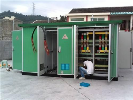
The above requirements currently give priority to the application of 380V and above voltage level box type substation (eg American transformer substation, European substation, etc.), 110KV, 220kV, 500kW substation switch cabinet, transformer and other power system equipment. The following figure shows the power equipment of wireless sensor application.
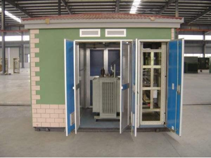
oil transformer, with external switch
Dry Tranformer
SF6 gas filling cabinet
.png)
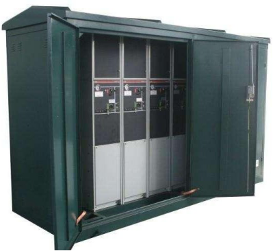
Air insulated switchgear
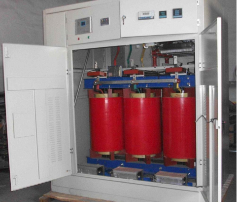
Dry transformer Cabinet
The wireless network is used to connect the components inside the power equipment and between the power equipment, and the auxiliary facilities such as the public communication network, cloud and intelligent terminal are used to realize the condition monitoring of power equipment components and power equipment, To achieve intelligent prediction of key parameters of power equipment such as energy consumption, life, potential failure, etc., provide accurate and predictable operation information for users, and realize high-quality operation and maintenance decision-making of users.
System composition
Wireless terminal, data collector, gateway, cloud, intelligent terminal.
Function introduction
Wireless sensor is used to measure temperature, humidity, partial discharge and arc light of key nodes of power equipment or components (such as transformer low-voltage copper plate lap joint, circuit breaker contact, power equipment environment), and ensure the safe operation of electrical equipment or components through environmental parameter monitoring.
The wireless host exchanges data with wireless sensors (temperature, partial discharge, arc light, humidity) through RF signals (433, 2.4G, nb-iot). The sensor data collected by the wireless host is uploaded to the local server of the power equipment through the measurement and control device for localized operation and maintenance. It can also be connected with the cloud through the Internet of things gateway to realize remote viewing of various terminals (PC, personal terminal).
Technical index
Sensing layer: composed of various sensors, including wireless temperature sensor, wireless partial discharge sensor, wireless arc sensor, wireless SF6 gas monitoring sensor, wireless humidity sensor, etc.
Wireless temperature sensor
Wireless Temp. Sensor |
technical parameters | Allowable values of wireless temp. Sensor |
| Temperature measurement range | -40℃~150℃ | |
| Temperature accuracy | ±0.5℃ | |
| Transmission distance |
up to 10000 m (LORA mode, open environment) |
|
| Network type |
star |
|
| Wireless frequency |
433M / 2.4G ism free band |
|
| Sensor node channel | 1-400 | |
| Sensor node network ID range | 1-65535 | |
| Sensor node address range | 1-65535 | |
| Structural form |
integrated ABS engineering plastic and metal shell are optional | |
| Power supply mode | permalloy ring power supply (CT power supply) |
|
| Waterproof grade | IP65 |
Wireless sensor for PD intensity measurement
Wireless partial discharge |
technical parameters | Allowable values of wireless temp. Sensor |
| Dynamic range |
0-75dB | |
| Working independently | for 10 hrs continuous measurement |
|
| Automatic shutdown | for 15 minutes |
|
| Working temperature | -20℃-55℃ | |
| Storage temperature | -40℃-75℃ | |
| Supply voltage battery powered | 9V | |
| Sensor node network ID range | 1-65535 | |
| Sensor node address range | 1-65535 | |
| Structural form | integrated ABS engineering plastic and metal shell are optional |
|
| Waterproof grade | IP65 |
Wireless PD intensity measurement sensor can detect live PD of cable accessories, such as cable head, arrester, insulator, bushing, etc. The PD level is displayed on the remote terminal. The remote terminal displays the DB value measured by the wireless PD intensity measurement sensor. The DB value changes with the discharge indicator on the wireless PD intensity measurement sensor. The range is 0-75db and "ol" is displayed when the reading exceeds its maximum range. The reading of the PD intensity as a simple intensity level indication is proportional to the probability of failure in the voltage fittings under test. The wireless partial discharge measurement intensity sensor is composed of UHF sensor, TEV sensor and ultrasonic sensor.
Wireless arc measuring sensor: (technical requirements refer to DL / T 1504-2016 < General technical conditions for arc protection device >
The arc light protection sensor is installed in each compartment of the switch cabinet. When the arc light is generated and burned, the light intensity and load current will increase suddenly. The arc light sensor sends out information through the change of light induction (it can also detect the change of load current at the same time, and make comprehensive judgment), so as to judge the value change of the arc light sensor When the setting value is exceeded, it will be transmitted directly to the wireless receiving host. Through the rapid detection of arc light, it can resist the strong electromagnetic interference when the circuit breaker is disconnected, and the trip signal output time is short.
Wireless SF6 gas monitoring sensor
SF6 gas has been widely used in power system because of its excellent insulation and arc extinguishing performance. It is almost the only insulation and arc extinguishing medium used in medium voltage, high voltage and ultra-high voltage switches. Because of the large use of SF6 gas, its safety has been widely concerned. Objectively speaking, SF6 gas is a colorless, odorless, heavier than air density, not easy to mix with air, no toxicity to human body. However, under the action of high-voltage arc or high temperature, SF6 gas will be partially decomposed, and its decomposition products often contain highly toxic, even a small amount of them can also cause human death. When the indoor switch using SF6 gas as insulation and arc extinguishing medium leaks in the process of use, the leaked SF6 gas and its decomposition products will accumulate in the lower indoor space, resulting in local hypoxia and poison, which constitutes a serious danger to the life safety of indoor workers
SF6+O2 Sensor |
technical parameters | Allowable value |
| SF6 Measurement Index | ||
| The measurement range | 0-30000ppmv | |
| Alarm point | can be set within the measurement range, the default is 1000ppmv | |
| Reference error | ±5%FS | |
| Repeatability error | <5%FS | |
| Zero drift | <5%FS | |
| Range drift | <5%FS | |
| Oxygen measurement Index | ||
| Detection concentration | 0~25% | |
| Oxygen concentration alarm point | 18% | |
| The accuracy of oxygen measurement | less than 0.4%, when O2 is 21% |
Network layer: wireless host, public network access gateway
Wireless host: the wireless host is used to receive various wireless sensor signals in the power equipment body. The wireless host can receive various types of wireless sensors independently, or integrate and receive all types of wireless sensors at the same time. The wireless host needs to configure alarm threshold, sampling period and other parameters, and can also store the collected data for a short time and export the data to the PC for viewing. The wireless host has the function of on-line real-time display of wireless sensor data, and also has RS485 interface to communicate with other devices. The wireless host is configured with a hardware port connected to the cloud.
Public network access gateway: 2G / 3G / 4G / 5G internet terminal, nb-iot Internet of things terminal
Cloud: provide sensor location, data display, historical data query (query by conditions), data analysis (based on multi-dimensional data information for power equipment potential risk prediction, user rights management.)
Terminal: according to the user login information, thousands of people and thousands of faces can be realized.
Application scenariosThe above requirements currently give priority to the application of 380V and above voltage level box type substation (eg American transformer substation, European substation, etc.), 110KV, 220kV, 500kW substation switch cabinet, transformer and other power system equipment. The following figure shows the power equipment of wireless sensor application.
oil transformer, with external switch
Dry Tranformer
SF6 gas filling cabinet
Air insulated switchgear
Dry transformer Cabinet
Technical specifications of the mode
Number of receiving wireless temperature measurement sensors: 256
Communication method RS-485/Ethernet/GPRS network
Working voltage: DC12~24V
Storage mode: Native Flash storage
Collection cycle 1~240 minutes (adjustable)
Alarm mode buzzer
Frequency range 433MHz
Communication protocol Modbus
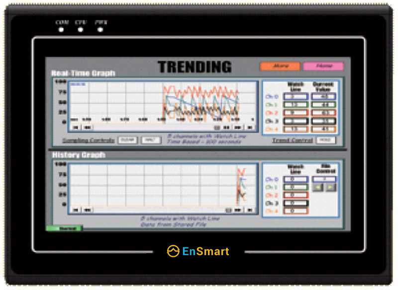
Display function 7-inch color screen (can display electronic map, alarm data, historical data)
Resistive touch screen operation
Communication method RS-485/Ethernet/GPRS network
Working voltage: DC12~24V
Storage mode: Native Flash storage
Collection cycle 1~240 minutes (adjustable)
Alarm mode buzzer
Frequency range 433MHz
Communication protocol Modbus
Display function 7-inch color screen (can display electronic map, alarm data, historical data)
Resistive touch screen operation